Lab 1: Measuring VoltageThe circuit was using a switch to increase the voltage for the change in measurement.
The circuit board has connection points that connect to each other on both sides of it. And all of the wires are placed in those connection points, connecting to each other as well as a switch and a 1K Ohm Resistor. The power supply is placed at 6 volts which is what the measurement should be when the switch is turned on and the voltmeter is measuring (connected to) the 1K Ohm Resistor. And when the switch is turned off, the voltmeter measures little to no measurement at all, because with the switch turned off, the full amount of voltage can flow through with the rest of the circuit. The significance of this circuit is that we are measuring in voltage with a multi-meter to see the difference between the measurement of voltage with the switch on, and with it off. |
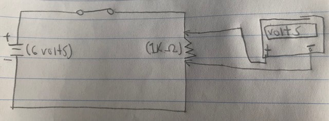

(Up above is a re-imagined drawing from the circuit)
(Actual pictures of both circuits were forgotten to be taken) |
Lab 2: Measuring CurrentJust like with measuring voltage, the circuit is equipped with a switch to turn on and off changing the measurement of current.
This new circuit is basically, and electronically the same as measuring voltage, and that when the switch used in the circuit is turned on, the amount of what is being measured should be in measurement by the ammeter. The difference in this circuit is that when it comes to measuring current, the current must flow through the ammeter. So it needs to be in series with the 1K Ohm resistor. Otherwise, the ammeter must become a part of the circuit to measure the current within it. The significance of this circuit is how different it is compared to the measuring voltage circuit. And with that being said, the reason why we cannot have the ammeter be parallel with the 1K Ohm resistor like in measuring voltage, is because if it is, the ammeter will have resistance. And with resistance, the ammeter will only increase the circuit's resistance and will decrease the flow of current for as long as the ammeter is connected. |


|
Lab 3: ThermocouplesThe multimeter is set to measure voltage, and it does so by using a thermocouple to measure the voltage through a flame from a lighter.
Thermocouples are two different metal wires twisted together to measure voltage through heat. And with the way how metal gets super hot when heat touches it for a long amount of time, the wires get hot and with a voltmeter connected, it will measure voltage through the wires, because inside, atoms and molecules start moving around inside the metal making it hot, making the voltmeter measure voltage. This experiment is important, because we learn how voltage can be measured by heat through metal. It also explains why we get burnt when heat is applied to metal we touch in the kitchen. |


|
Lab 4: Photovoltaic CellsThe multimeter is using a photovoltaic cell to measure voltage through bright light.
Photovoltaic cells are photosensitive like solar panels and photocells, meaning they are sensitive to light and power devices used in circuits they are connected to. The light from the sun or Solar Energy has been used for so many years that the reason why it is so hot, is because it has so much voltage. And we transform that Solar Energy into Electrical Energy to power our devices and technology. In this case we are using room temperature to measure about 5.2 millivolts, because the cells take in the light, and the amount of light reveals the result of millivolts on the millimeter. This is important, because we are measuring voltage through light. It helps us understand more of how solar panels can take in solar energy to power our homes. |


|
Lab 5: AA Battery (Double A)The multimeter is set to measure voltage while connected to a Double A battery.
All batteries (AAA, AA, C, D, and PP3) contain cells that are about 1.5 volts each. The AA Battery in the photo contains only one, which is why the multimeter is measuring 1.317 volts which is close to 1.5 when the clips touch both ends of the battery in the correct polarity. The importance of this experiment is that the double A battery in the picture is one of the rechargeable kinds of batteries. Which makes sense why the multimeter is measuring below 1.5 Volts, because power is already or has already been used by the battery, and it can be charged again, so there is no problem when it gets to low of power so that it can be recharged. |

|
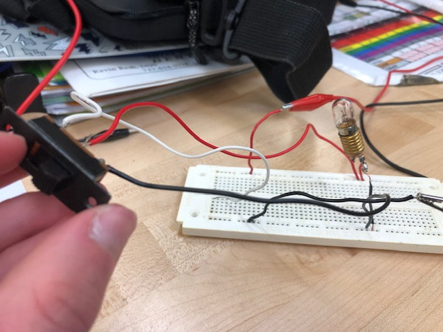
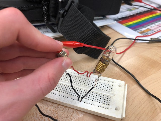
Lab 6: Switches (SPST, PBNO, PBNC)The circuit is using a SPST (Single Pole Single Throw), PBNO (Push Button Normally Open), and a PBNC (Push Button Normally Closed) switches to turn on a light bulb.
In order for a specific switch to properly work a device to switch on and off, both devices must be following or flowing in the correct polarity while having a power supply at 6.3 Volts following the flow of electrons. When the SPST and PBNO are in the open position, it turns the light/lamp on, but when the PBNC is open, the lamp is now already off. The polarity is switched between the two push buttons and not just the colors of the buttons themselves. The significance of this lab is to use a SPST switch. All three switched are classified as SPST, meaning that no matter which one, it is one circuit, one device that the switches are trying to function. And we learn that SPST switches is either open or closed, and is never partly open or partly closed, and in the open position, the conducting path is removed for the SPST, and for the Push Buttons, momentary actions (the spring within the push buttons are actuated to remain open for the PBNO, and to be actuated to remain closed for the PBNC) take place. |

|


Lab 7: Switches (SPDT, DPST, DPDT)The lab is using either a SPDT (Single Pole Double Throw), a DPST (Double Pole Single Throw), and DPDT (Double Pole Double Throw) Switch to turn on the light(s).
What makes the SPDT, DPST, and the DPDT switch so different from the other kinds of switches, is that there are more wiring to be done, because there are both more poles (separate circuits), and more throws (connected positions) the switch has to be connected to make the lab fully function. It does so by having the poles and throws labeled as numbers as well as the positions the wires are connected to on the switch. Each labeled pole and throw must be in the correct spots (as it says labeled-wise) for the circuit. It is the same deal with the one or two lamps in each circuit, the two sides must have labeled numbers connected to the circuit, and the polarity must match with the circuit and with the wires, lamps, and switch. The significance is using the SPDT DPST and DPDT switch in these circuit experiments, but also the specific areas the wires must connect to from the switch to the circuit and to the lamps. * The SPDT switch has only three wires soldered onto the switch. When I thought, "It would make sense for the circuit to look exactly as it is shown on the schematic diagram, it would work," (of course) it wouldn't. And the reason why is to follow not how the whole schematic diagram looks, but by how the pattern of the diagram looks and to follow the direct and correct numbered wires of the switch to the correct places. * The DPST and DPDT switches are actually the same physical switch shown in the pictures for the second and third experiment used in this lab. To make the switch that has six wires soldered on to it for being a DPDT switch, turn into a DPST switch is to only use four of the six wires, because it is a single throw and not a double throw which is the use for having all six wires. |

|


Lab 8: Three-Way SwitchThe circuit is using two SPDT switches to make a three-way switch circuit.
Like the previous two labs, the schematic diagram is showing what the component devices should be doing and not what it is physically supposed to look like. In this lab, we are now using two SPDT (Single Pole Double Throw) switches to make the light turn on and from both switches. How this is possible is that where the two upper throws meet above as well as the ones below (the line that is disconnected to the rest of the circuit) are both separate from the rest of the circuit. In the pictures below the schematic diagram, on the upper right picture you can see that the two white wires from both switches meet in the area of the circuit board where the most holes are in on the top side of the divider for the polarity to travel, while the two black wires from both switches are on the area below that line with most holes. This is how they connect to each other matching polarity while being connected to the rest of the circuit for whenever one switch turns the light on or off, the other light will either turn it back off or on. The significance of this lab is how it explains how switches at stairwells or hallways work when they are apart from each other, but are still connected to each other and to the light turning it off or on when the other switch does the opposite of either function. |

|


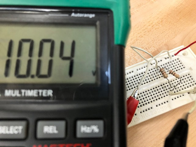
Lab 9: Ohm's LawThe circuit is to measure the resistors given in the lab of Voltage and of Current.
We first and only measure Voltage for the 1.5 K Ohm resistor while we measure Current also for the 1.5 K but also for the rest (1 K, 3.3 K, and 10 K [a 10 K Ohm resistor could not have been found so only these three resistors were measured in this experiment]). We measure Voltage by applying it into the circuit parallel across the resistor(s). While for Current, it is in series, because we are trying to measure the Current that is flowing throughout the entire circuit, so it must be a part of the circuit to measure it. And how that worked for the physical circuit, was to move the positive red wire of the power source from being in parallel to being in a separate area on the circuit board so that we can put the positive red wire of the multimeter in the same area as well so that it can remain in series without any interference with the flow at all. The significance of this circuit is how it reminds us how Ohm's Law states that Current flow is inversely proportional to resistance. Thus, for a constant value of applied Voltage, increasing the Resistance will decrease the Current flow and decreasing the Resistance will increase the Current flow which is what the Ohm's Law equations prove to us when we solve them. |

|


Lab 10: Watt's LawThe circuit is to be measured by both a milliammeter to measure milliamps and a voltmeter to measure volts with two 100 Ohm resistors connected in parallel with each other.
To measure amps, the ammeter must be in series with the circuit, becoming a part of the circuit, so that it can measure the current flow. To measure volts, the voltmeter must be in parallel with the circuit so that doesn't interfere with the flow of electrons/ current. With two resistors in parallel, they cannot be physically connected with the rest of the circuit as shown in the schematic diagram. So the resistors are in parallel separate from the rest of the circuit, but with jumper wires connected so that they are electrically connected. The significance of this circuit is that after measuring the it with 2 volts, 2 more volts are added after every measurement of current until it gets to ten volts. And the reason why we are doing so, is so that we can practice using Watt's Law to calculate for Wattage with the amount of voltage and amperage (current) shown (P=ExI). And also the fact that two 100 Ohm resistors equal one Watt. |

|

Lab 11: Watt's Law (Continued)The circuit is to be measured of voltage and amperage, but with a lamp instead of two 100 Ohm resistors to determine if the lamp's resistance varies with the temperature given off when it is activated.
To measure voltage, once again the voltmeter must be parallel in the circuit to the lamp, and after a volt is added, the lamp gets brighter. And as for current, the lamp itself doesn't need to be on itself to measure for current, but it still needs to be in series with the circuit. Therefore, the positive red wire from the power source must be physically separate, but electronically connected to the circuit. The significance is to add a volt after every measurement as well as calculation with Watt's Law to solve for power as well as for resistance with Ohm's Law. And as it turns out, that as filament current increases, power given off by the filament increases, raising its temperature until it glows. Thus, power is given off in the form of heat and light as the Power-Heat-Light lab packet says. |

|


